Aerodynamic Control with Plasma Actuators
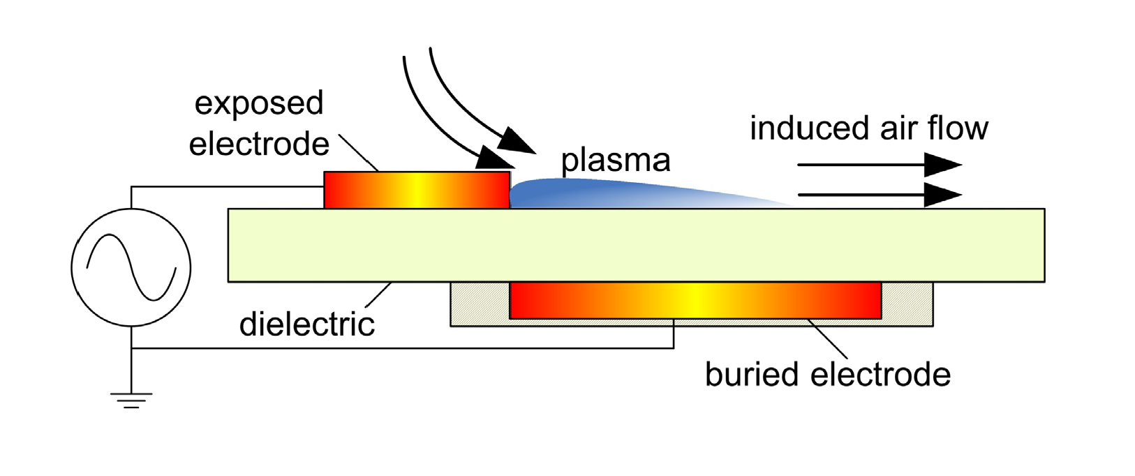
A dielectric-barrier-discharge (DBD) plasma is used to induce a flow close to a surface for flow control. The DBD plasma actuator consists of two electrodes separated by a dielectric barrier, Fig. 1. When a high voltage alternating current is applied, the air close to the exposed electrode is ionized, Fig. 2. |
|
| Figure 1: Schematic section of a DBD plasma actuator. |
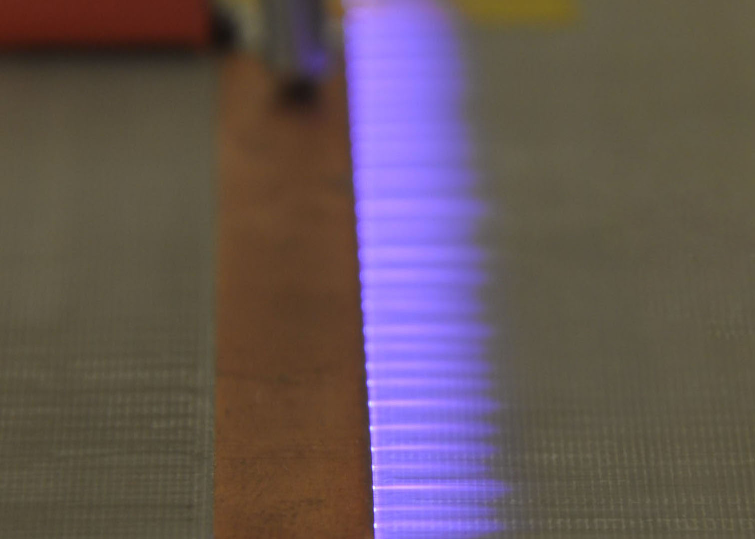 |
| Figure 2: Surface of a DBD plasma actuator in operation. |
On the surface the ions collide with the surrounding neutral air particles so as to transfer their momentum to the air. Therefore, the plasma actuator can be thought of as imposing a localized body force to the surrounding air. The aim of using this electric wind is in most cases to accelerate the airflow tangentially and very close to the actuator's surface in order to modify the local airflow profile, Fig. 3. |
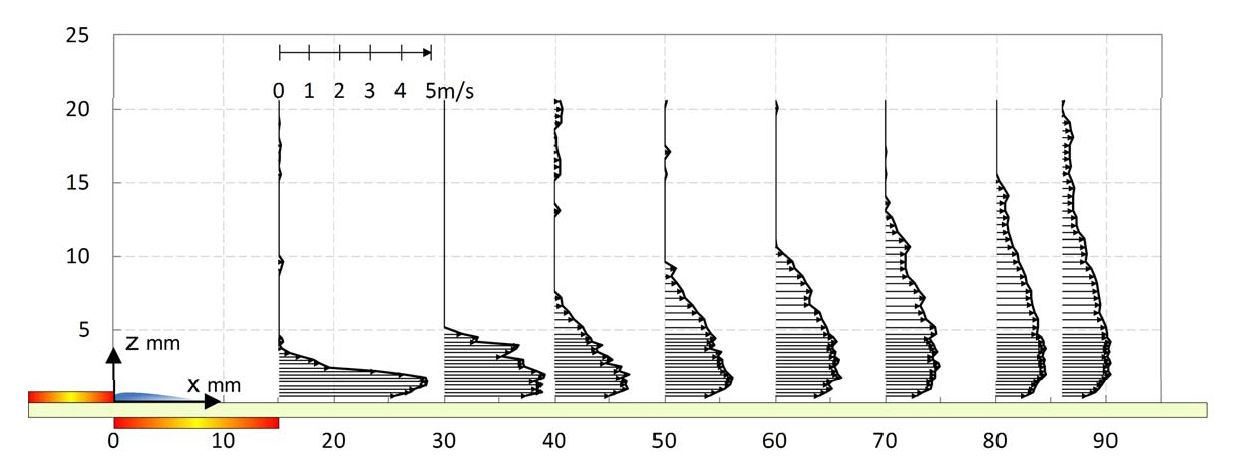 |
| Figure 3: Velocity profiles measured downstream of the exposed electrode for 25 kHz sinusoidal actuation of amplitude 6 kV. |
The main advantage of this process is that it directly converts electric energy into kinetic energy without involving moving mechanical parts. Secondly, its response time is very short and enables real-time control at high frequency. DBD plasma actuators are also light, small, and have little power consumption. Because of these desirable characteristics, in June 2009 the American Institute of Aeronautics and Astronautics named DBD plasma actuators one of the “Top ten emerging aerospace technologies”. |
The main disadvantage of DBD plasma actuators is the low efficiency of energy conversion they currently achieve.
Increasing their performance for aerodynamic control is one of the goals of the NUS Temasek Laboratories.
|
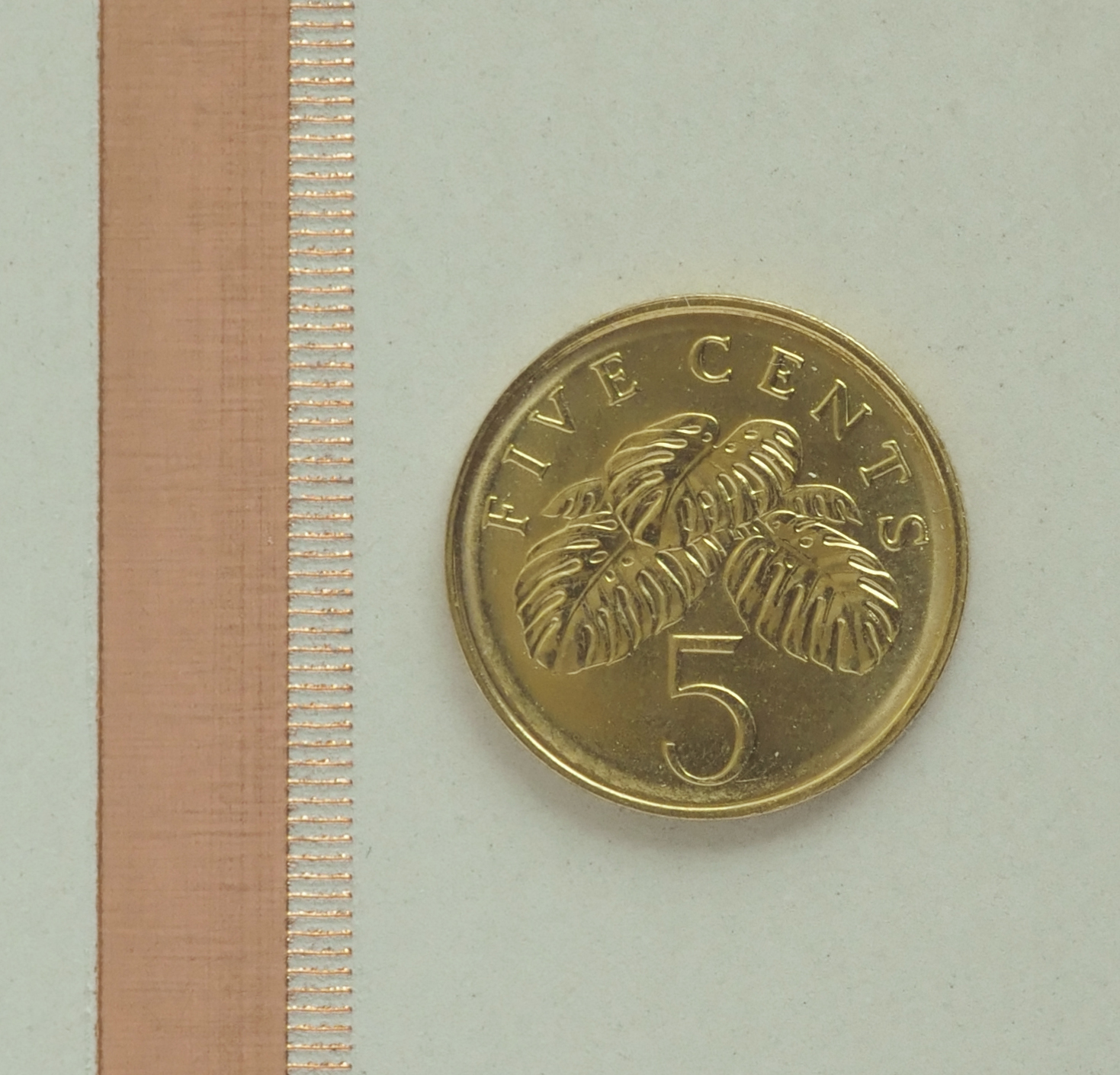 |
| Figure 4: Detail of exposed electrode with comb edge. |
We are also developing models of the DBD plasma actuator from which compensators will be designed to modify the actuator input so to produce an output that is flatter, possibly with higher magnitude and with better phase-matching for flow control applications.
At the same time we have explored a DBD-plasma driven channel flow.
The configuration consists of two DBD plasma actuators mirroring each other on opposite wall of a channel, Fig. 5.
The rationale is that a stronger flow could be obtained by merging the wall jets created by mirroring DBD plasma actuators.
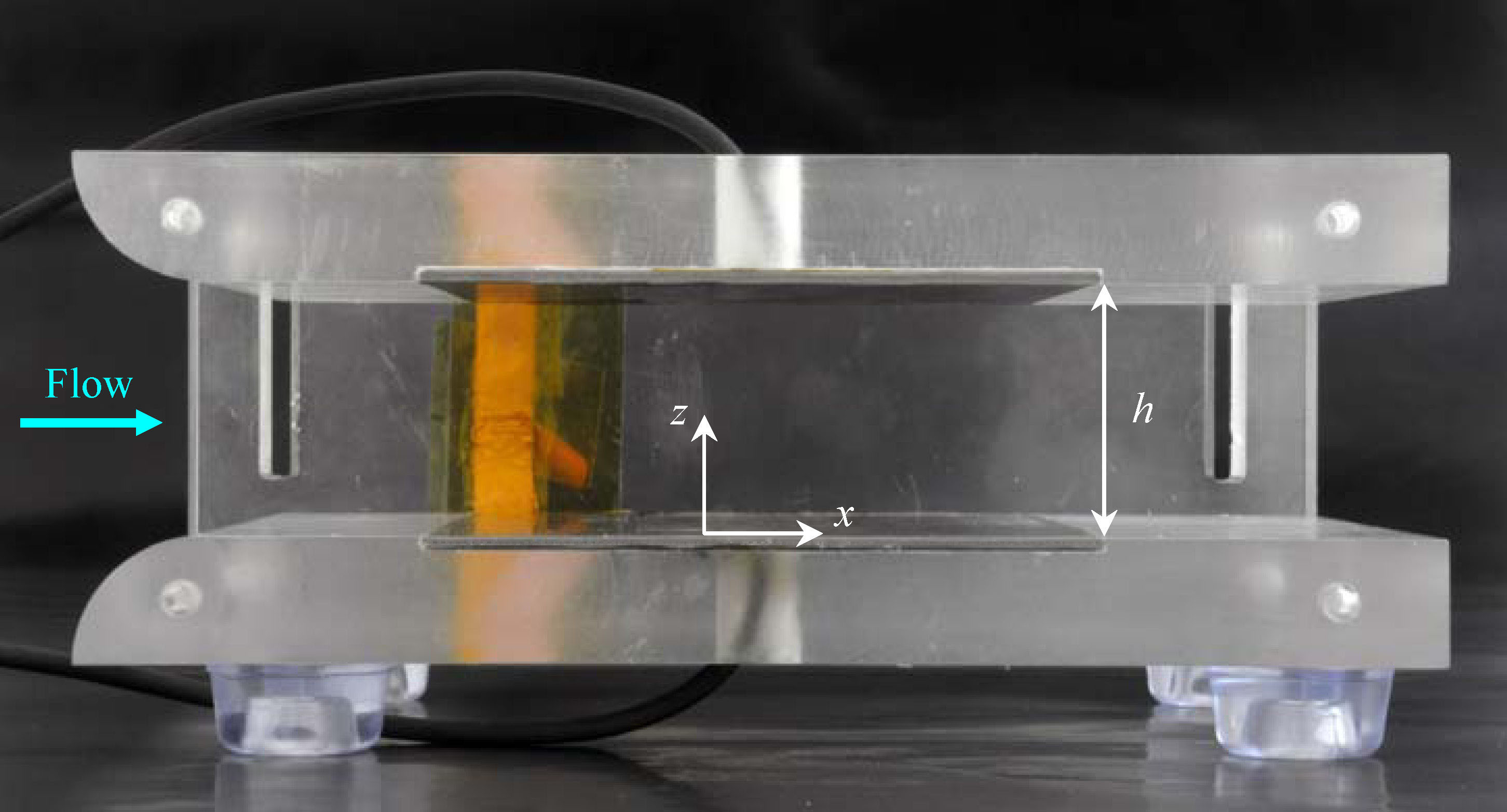 |
| Figure 5: DBD plasma channel. |
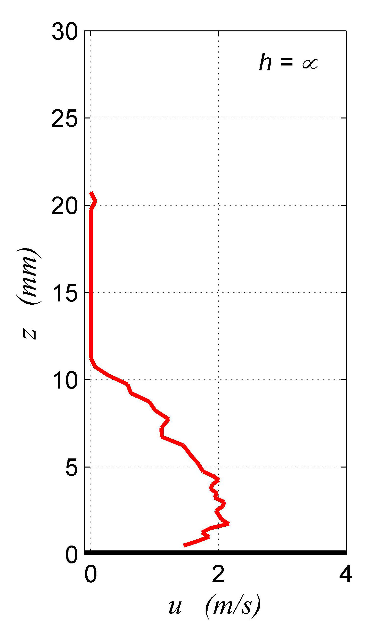
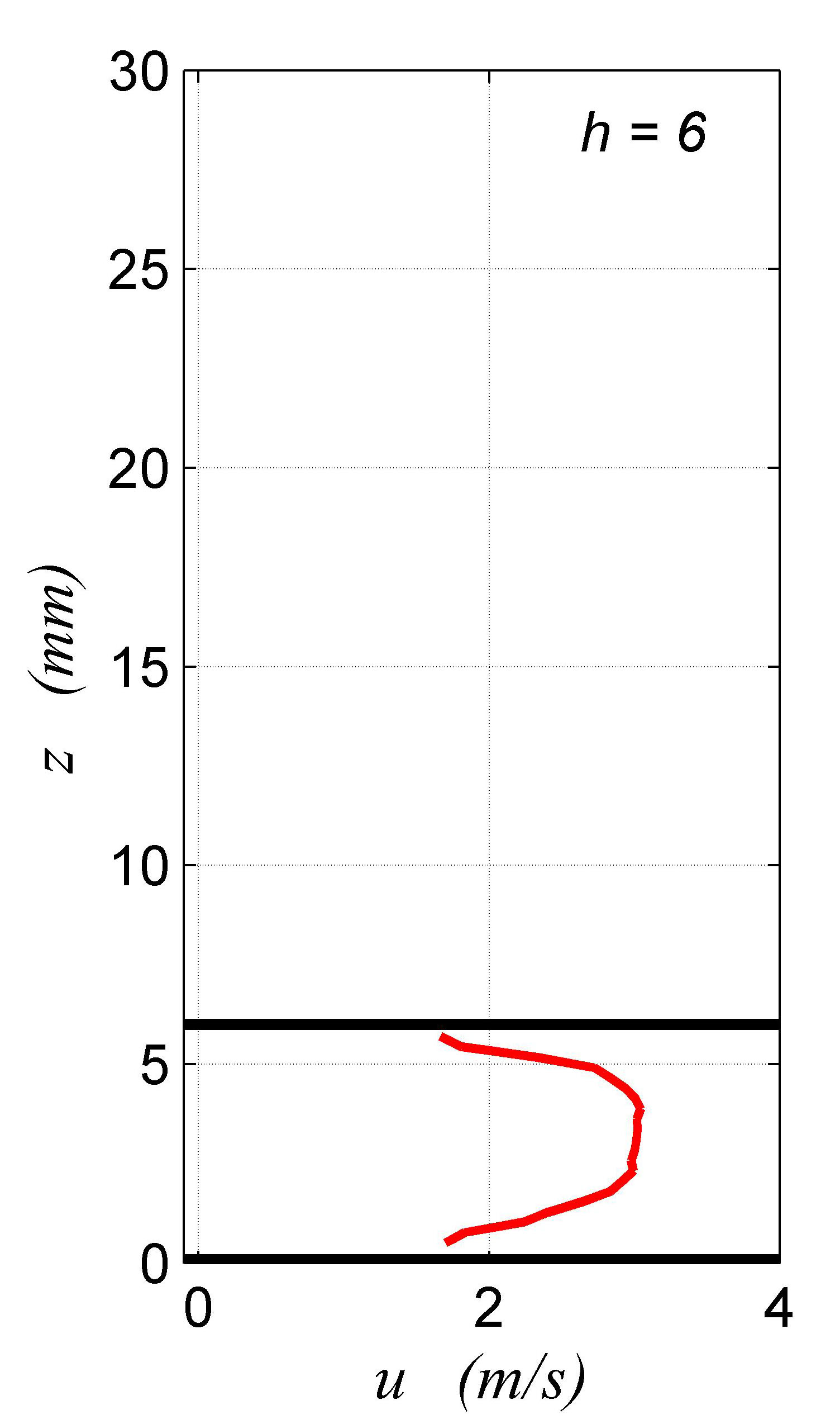
Measurements of the velocity of the channel flow have been performed for different values of the gap h between the mirroring actuators. The data are compared with the velocity of wall jets induced by a single DBD plasma actuator. The results indicate that the mirroring actuators produce independent wall jets for large values of the gap. As the gap decreases the wall jets merge and create a flow resembling the Poiseuille type. The merged flow in the channel has a velocity about twice that of the corresponding wall jet, Fig. 6. |
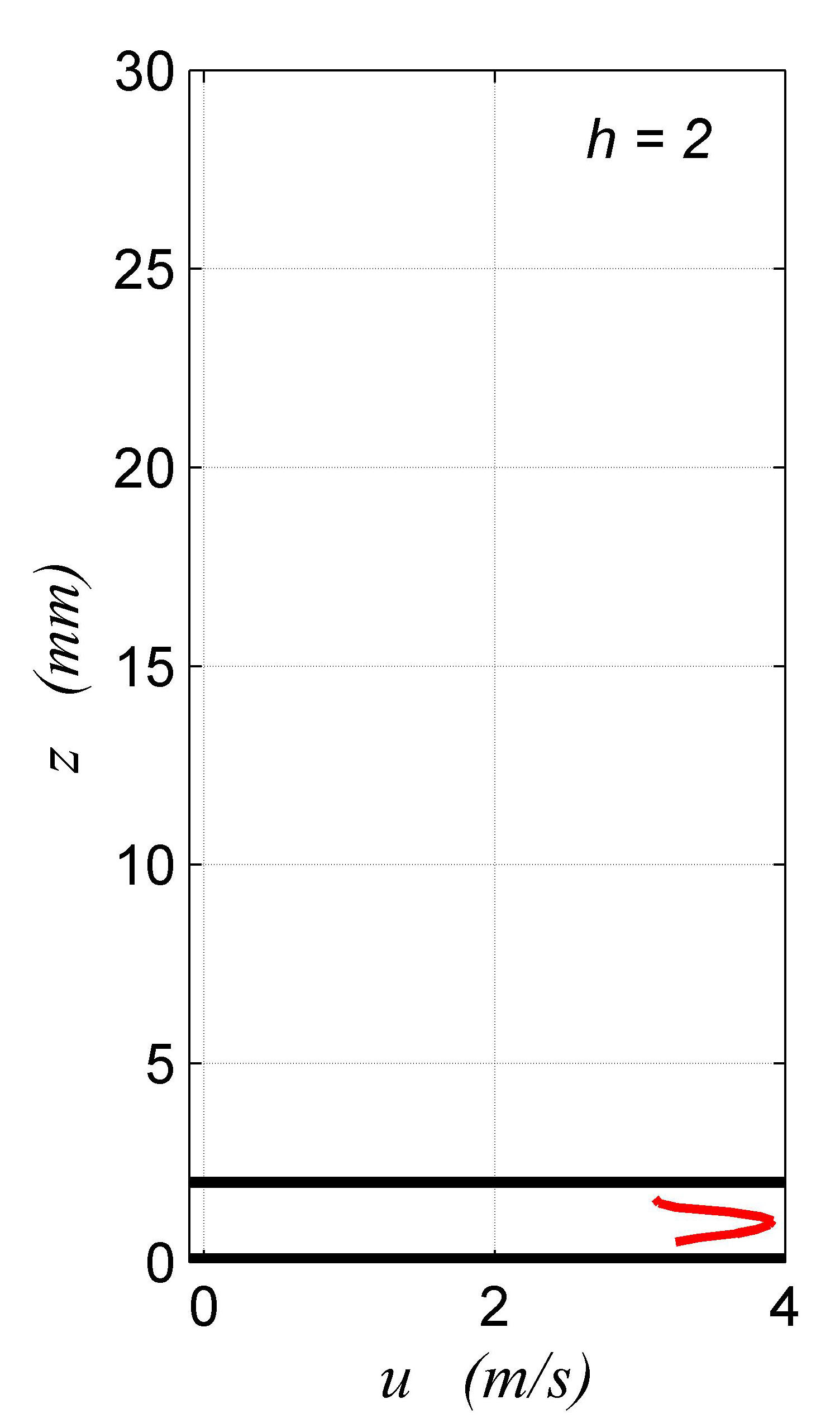 |
| Figure 6: Flow velocity profiles measured downstream of the exposed electrodes of a DBD plasma channel with sinusoidal actuation of amplitude 6 kV for: infinite gap (left), 6 mm gap (center), and 2 mm gap (right). The thick black lines indicate the position of the upper and lower walls of the channel. |
The preliminary results obtained suggest that DBD-plasma driven channels could be used to create small dynamic jets or suction devices for flow control applications.
|
| MD previous research | MD research | MD home |