Swept-back grid fins for reduced drag
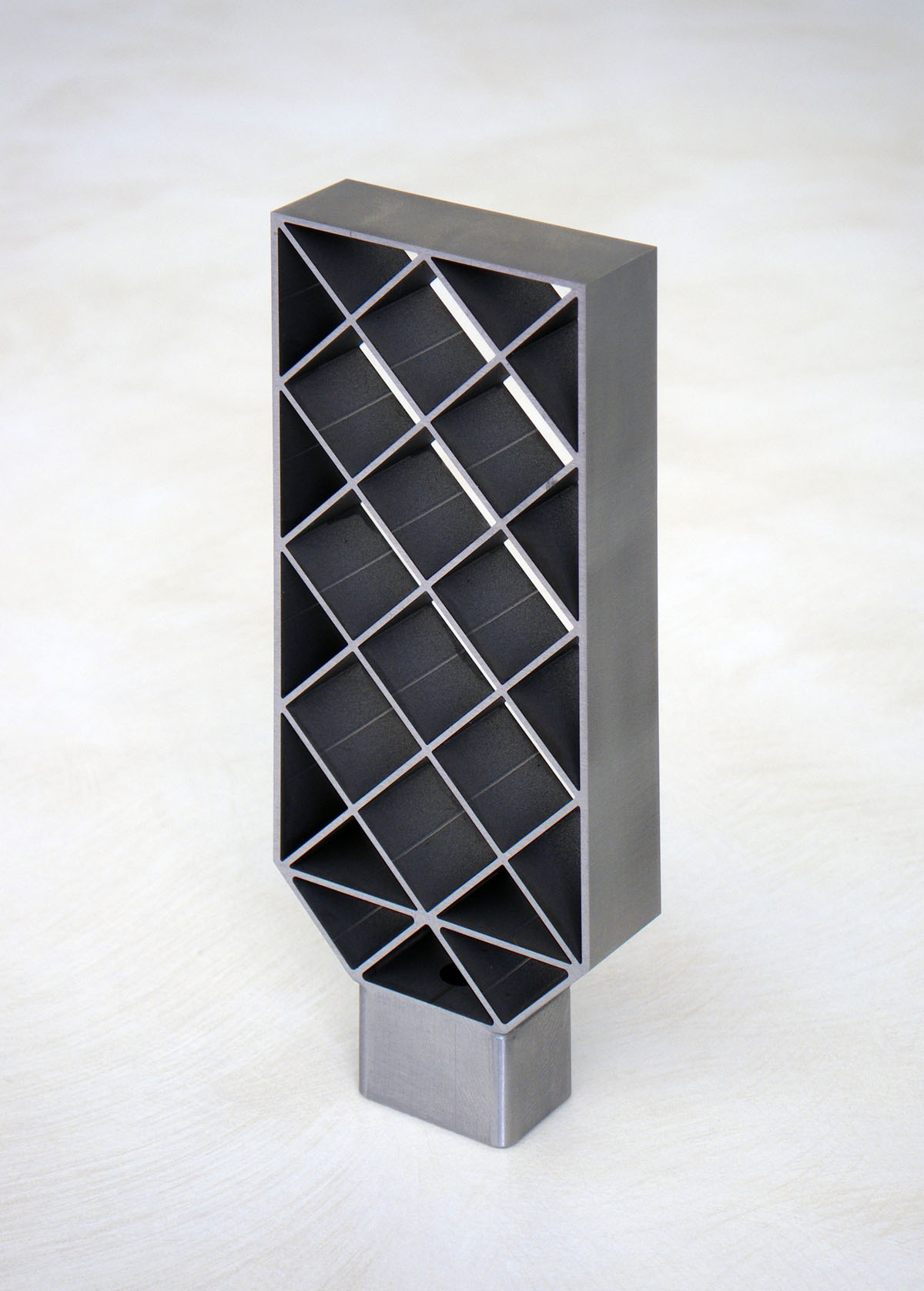
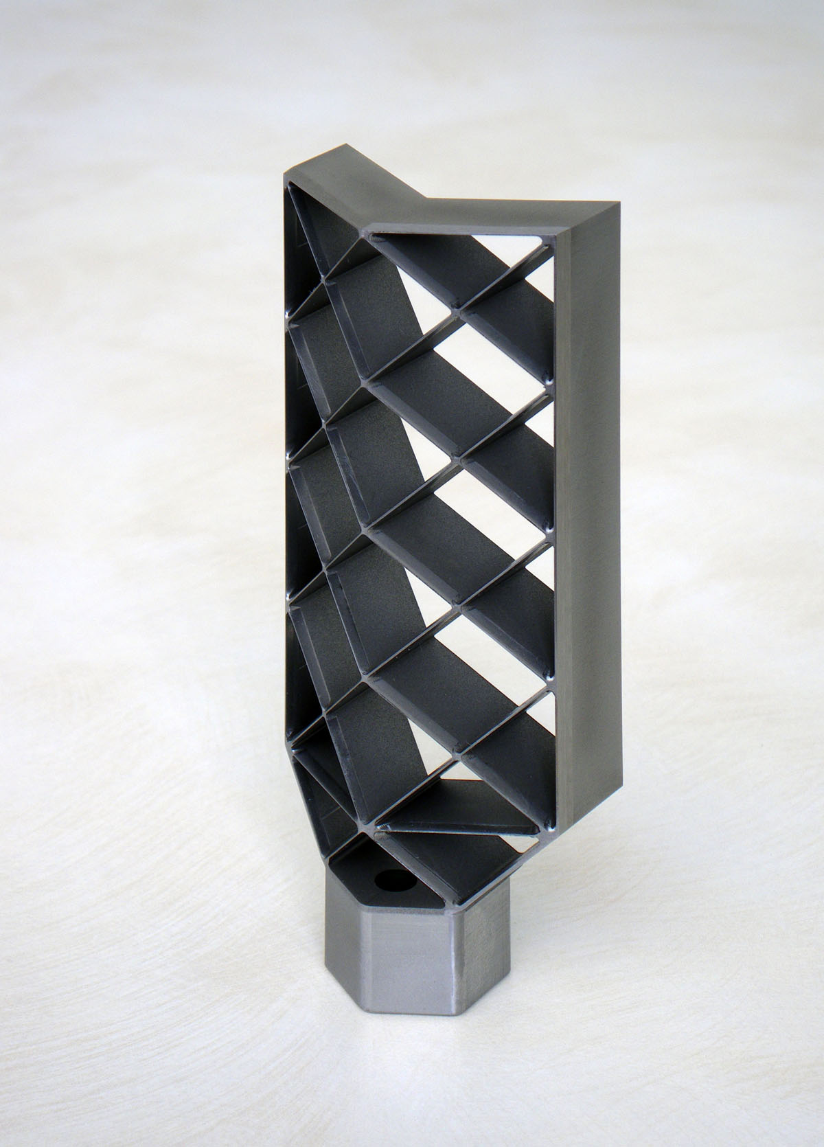
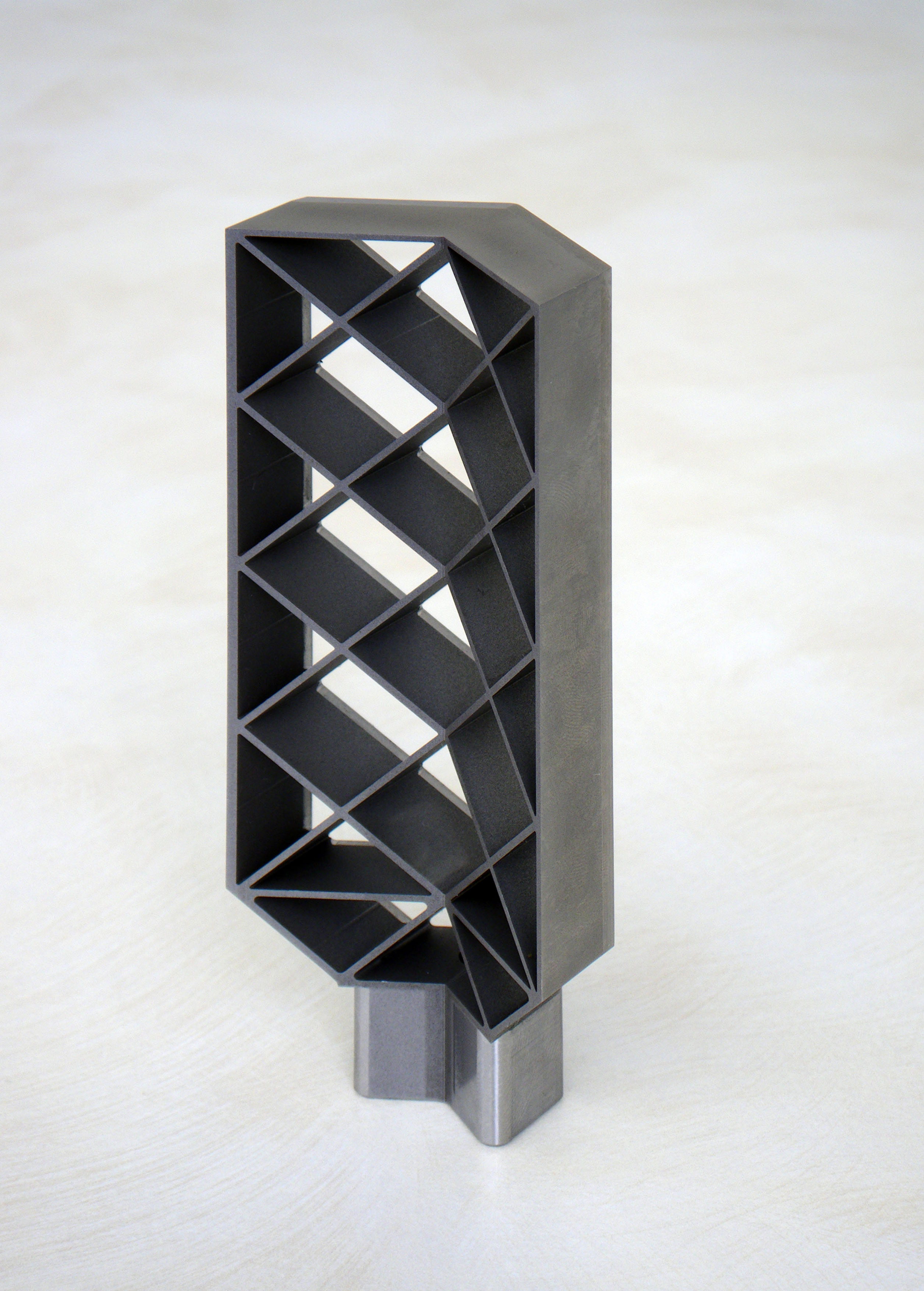
A grid fin is an aerodynamic control surface consisting of an outer frame with an internal lattice of intersecting thin walls of small chord, Fig. 1. Unlike planar fins that are aligned parallel to the direction of the airflow, grid fins are mounted perpendicular to the flow allowing the oncoming air to pass through the cells of the lattice. The main advantage of grid fins is that they have significantly smaller chord than planar fins. Thus, they generate smaller hinge moments which require smaller actuators to rotate them in a high-speed flow. Their small chord also makes them less likely to stall at high angles of attack which increases their control effectiveness compared to planar fins. Another advantage of grid fins is that they can easily be folded against an aerodynamic body to make them more compact and easier to store or transport. However grid fins of conventional "flat" design, Fig. 1 left, present higher drag than planar fins at transonic speeds. An angled (swept-back) grid-fin with sharp leading edges has been developed by the NUS Temasek Laboratories for reducing the drag close to the speed of sound, Fig. 1 right. |
|
|
| Figure 1: Conventional grid fin (left) and swept-back grid fin (right). |
The drag reduction of this configuration has been explored by using CFD simulations at transonic and supersonic speeds and zero angle of attack. These data were further validated with wind-tunnel measurements of models of the two types of fin in the transonic regime. |
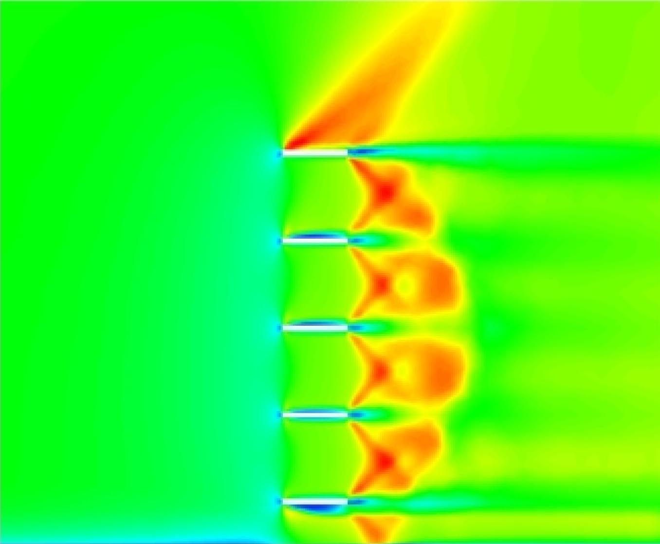
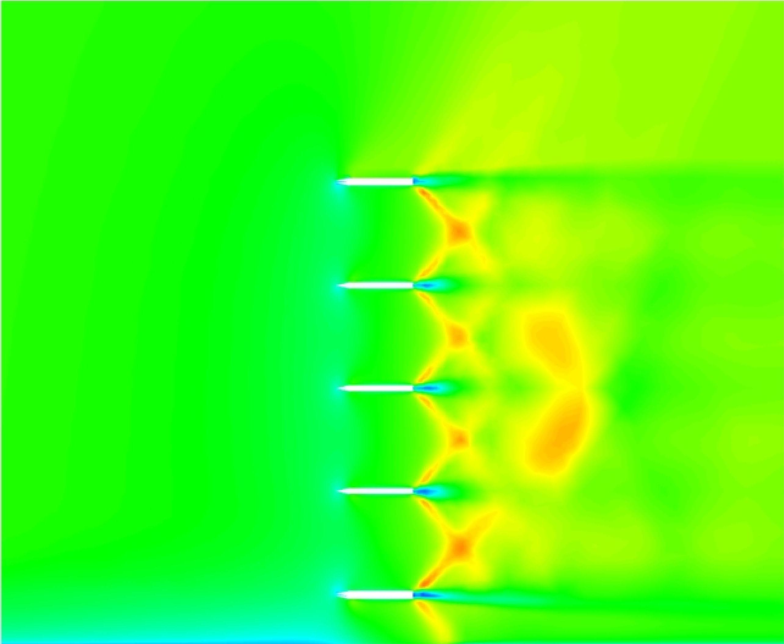
The results from CFD indicate that, compared to the conventional grid fin, the swept-back grid fin produces weaker shocks and expansions in the flow and promotes the passage of air through the fin lattice, Fig. 2. |
|
| Figure 2: Mach number contours across grid fins for freestream Mach number 1.045: conventional grid fin (left) and swept-back grid fin (right). |
The CFD results are confirmed by the experimental measurements, Fig. 3. Compared to the conventional grid fin, the swept-back type offers about 30% drag reduction in the transonic velocity range explored, Figure 3. |
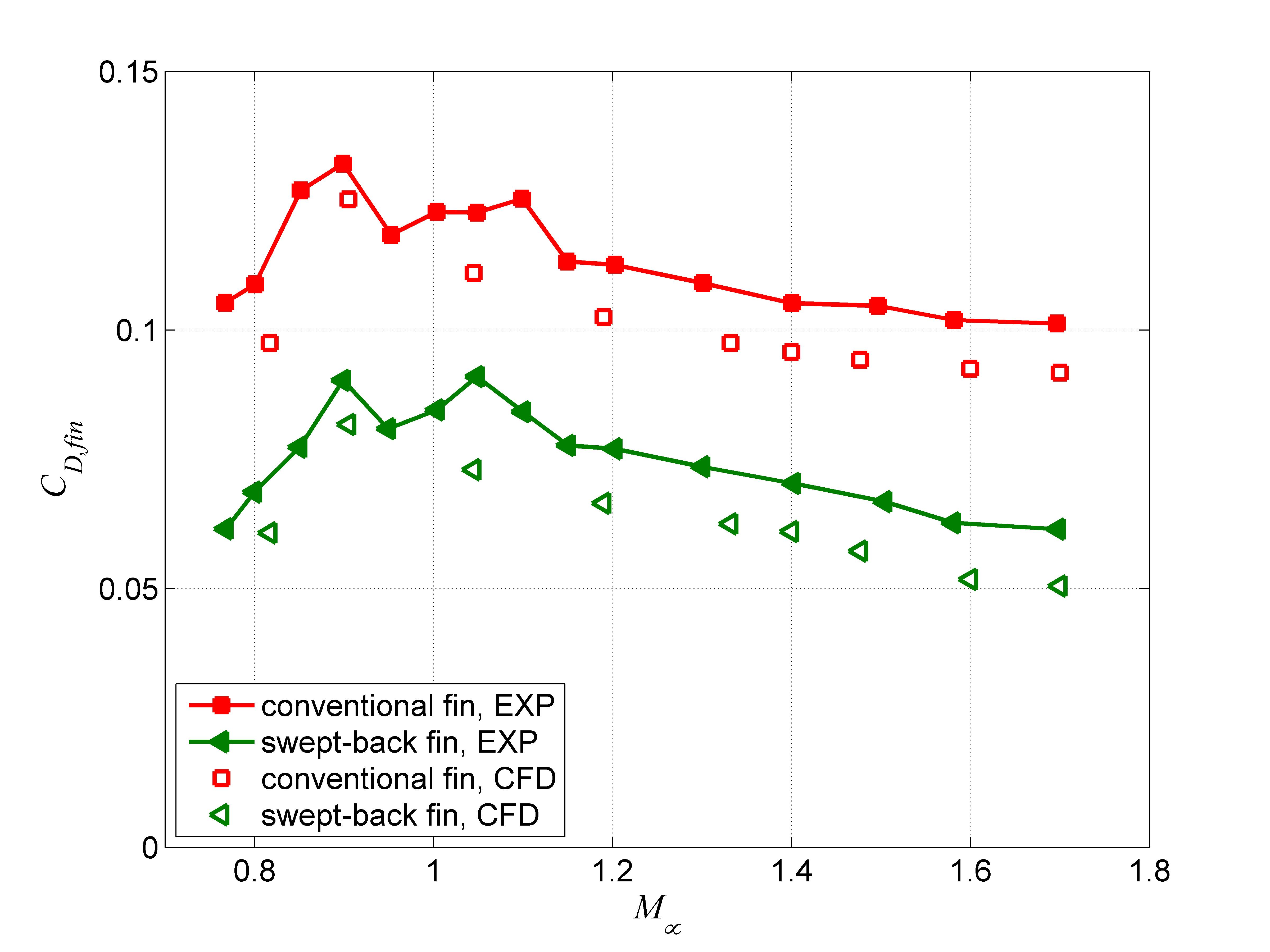 |
| Figure 3: Drag coefficient of grid fins from experiments and from numerical simulations. Swept-back grid fins have 30% less drag in the velocity range explored. |
The results obtained are described in more detail in:
|
 |
| Figure 4: Swept-forward grid fin. |
| MD previous research | MD research | MD home |