
at GDTL.
at GDTL.
Feedback-controlled air-supply system
I have worked as project manager of a feedback-controlled air-supply system that greatly enhanced the experimental capabilities at GDTL. |
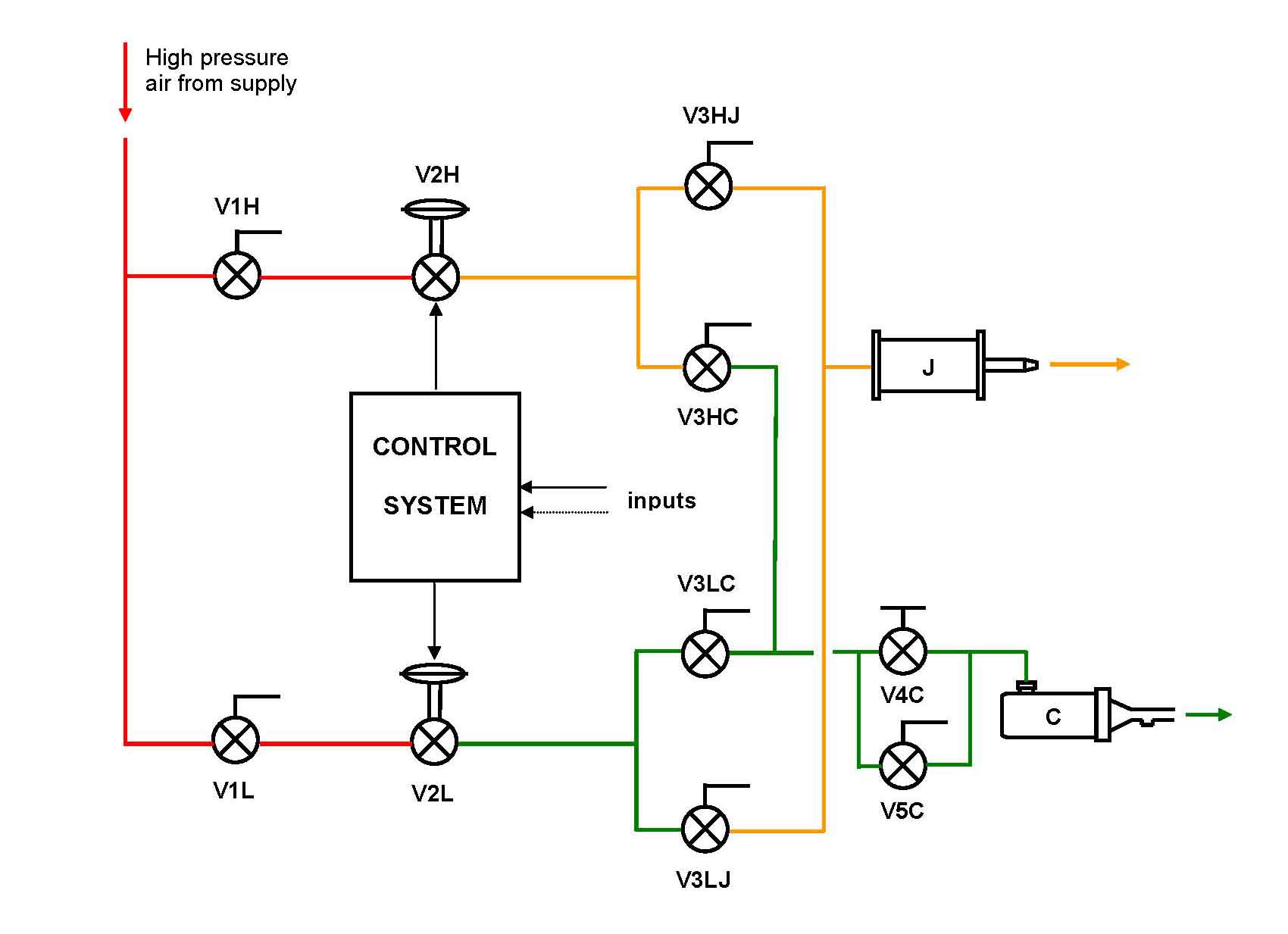
The facilities of GDTL operate with air stored in two high-capacity tanks at pressure between 1000 and 2300 psig. This high pressure, required for other experimental needs, is excessive for the GDTL uses and must be reduced and maintained to values between 1 to 250 psig regardless of pressure fluctuations in the tanks. To this aim two control valves are used: one for high mass-flow experiments, the other for low mass-flow experiments. Originally these valves were controlled by hand which required constant adjustments during the experiments. In 2004 I upgraded the system to include a feedback control unit operating the valves so to maintain automatically the stagnation pressure of the experiments to the desired value. Figure 1 shows a schematic of this air-supply system. V2H and V2L are respectively the high and the low mass-flow control valves and other isolation/distribution valves are also indicated. This system allowed GDTL to operate a cold jet facility J and the cavity-flow facility C. |
|
| |
| Figure 1: Schematic of old feedback-controlled air-supply system at GDTL. |
Figure 2: Schematic of new feedback-controlled air-supply system at GDTL. |
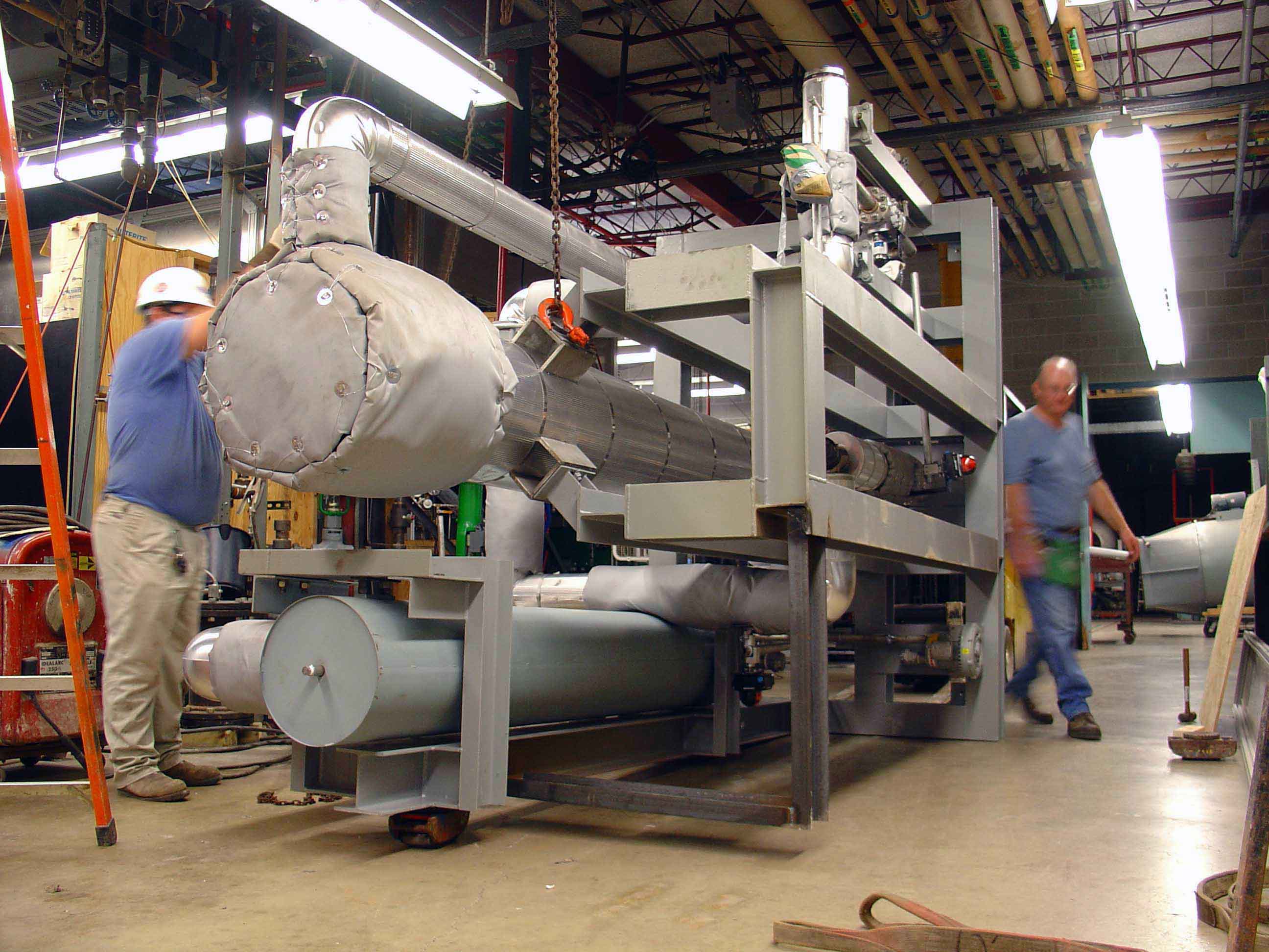
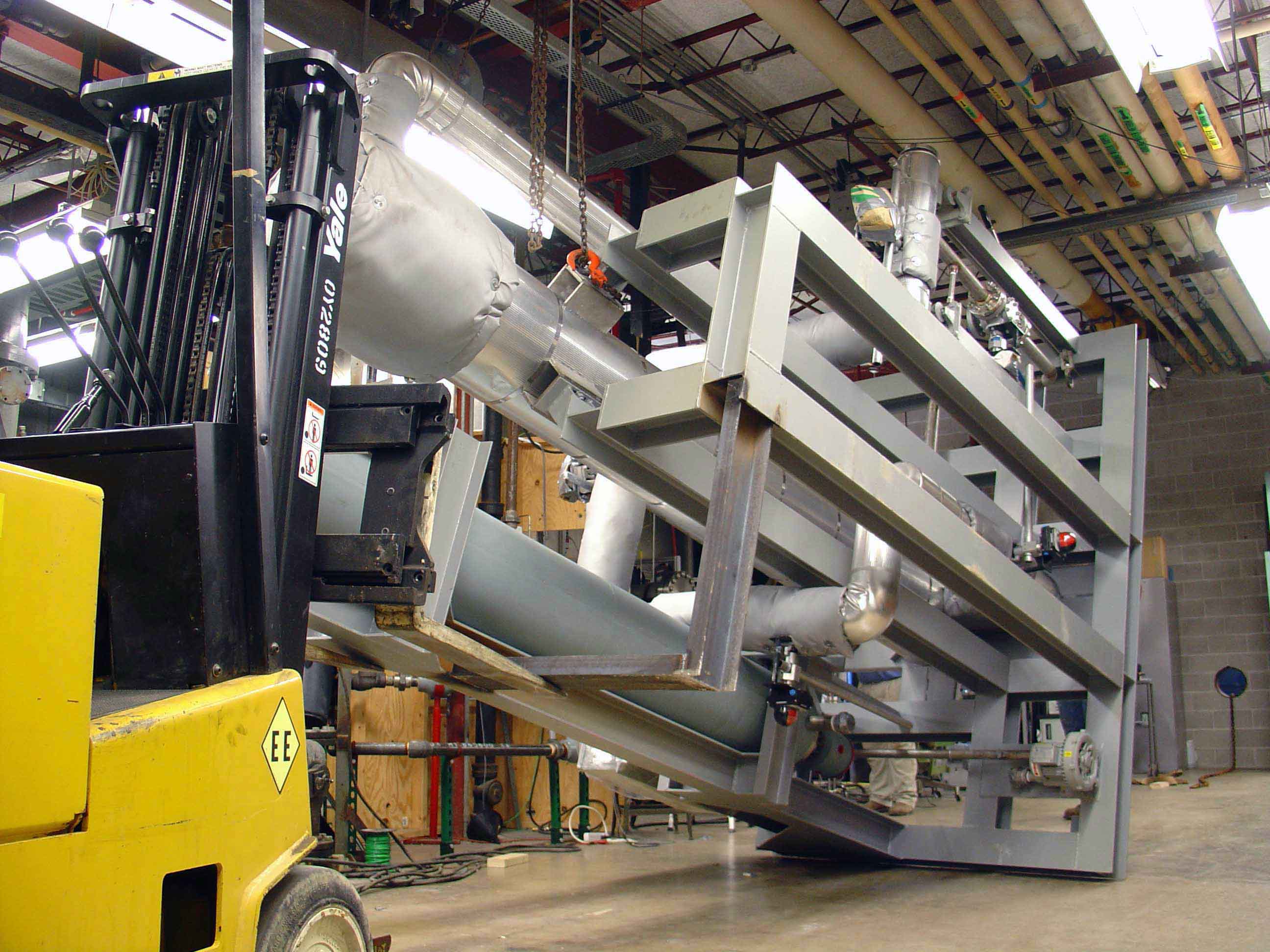
Working together with Aero Systems Engineering I created the new feedback-controlled air-supply system shown in Fig. 2 that dramatically increases the GDTL experimental capabilities. The jet facility J can now use both cold and hot (up to 1100 F) air and can be surrounded by a large secondary stream to simulate the effect of forward flight up to Mach 0.3. Figure 3 shows the roll-in, raise, and final setup of the regenerative storage heater and the jet facility. |
 |
 |
 |
| Figure 3: Regenerative storage heater roll-in (left), raise (center), and final setup with the jet facility (right). |
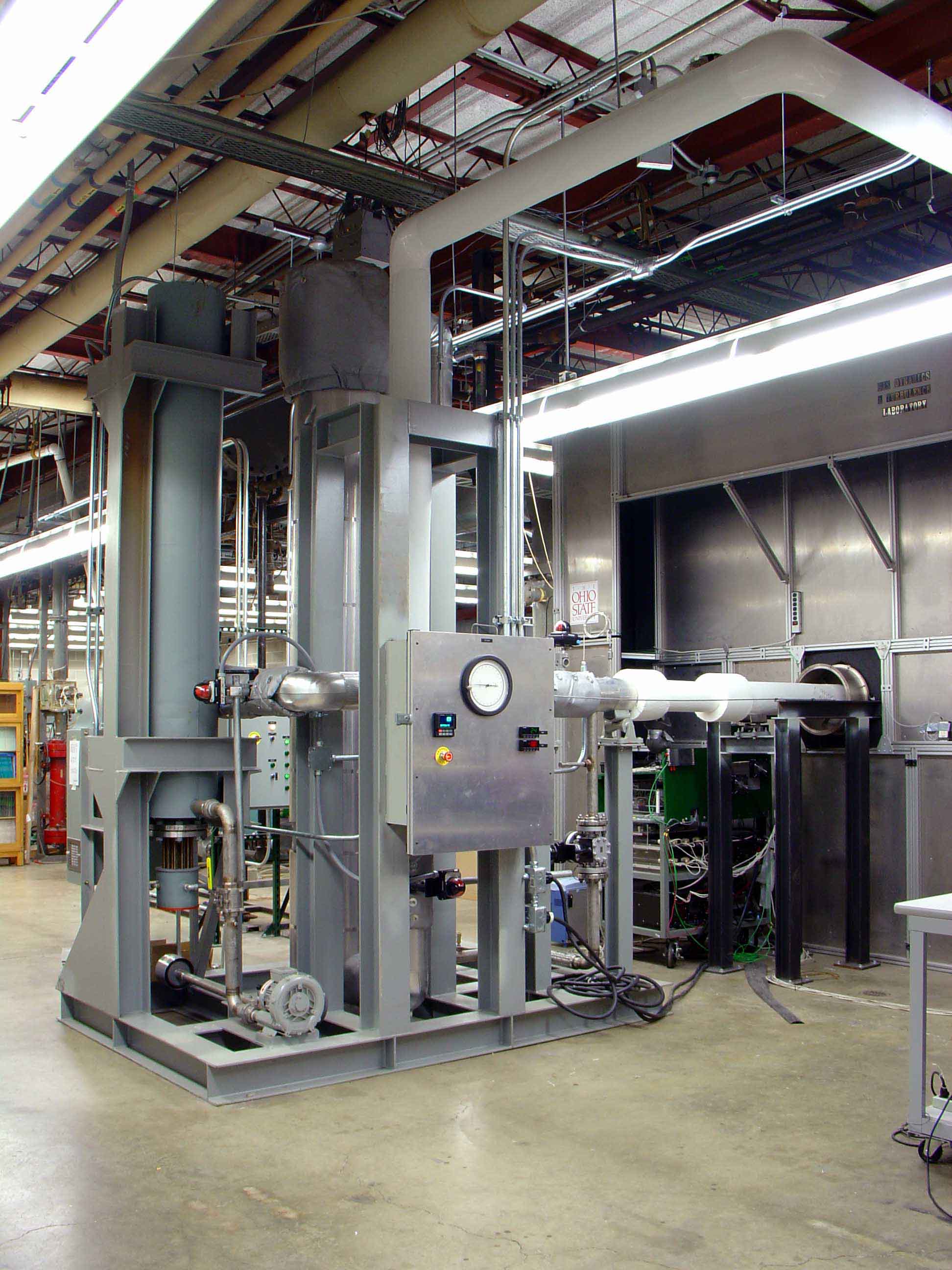
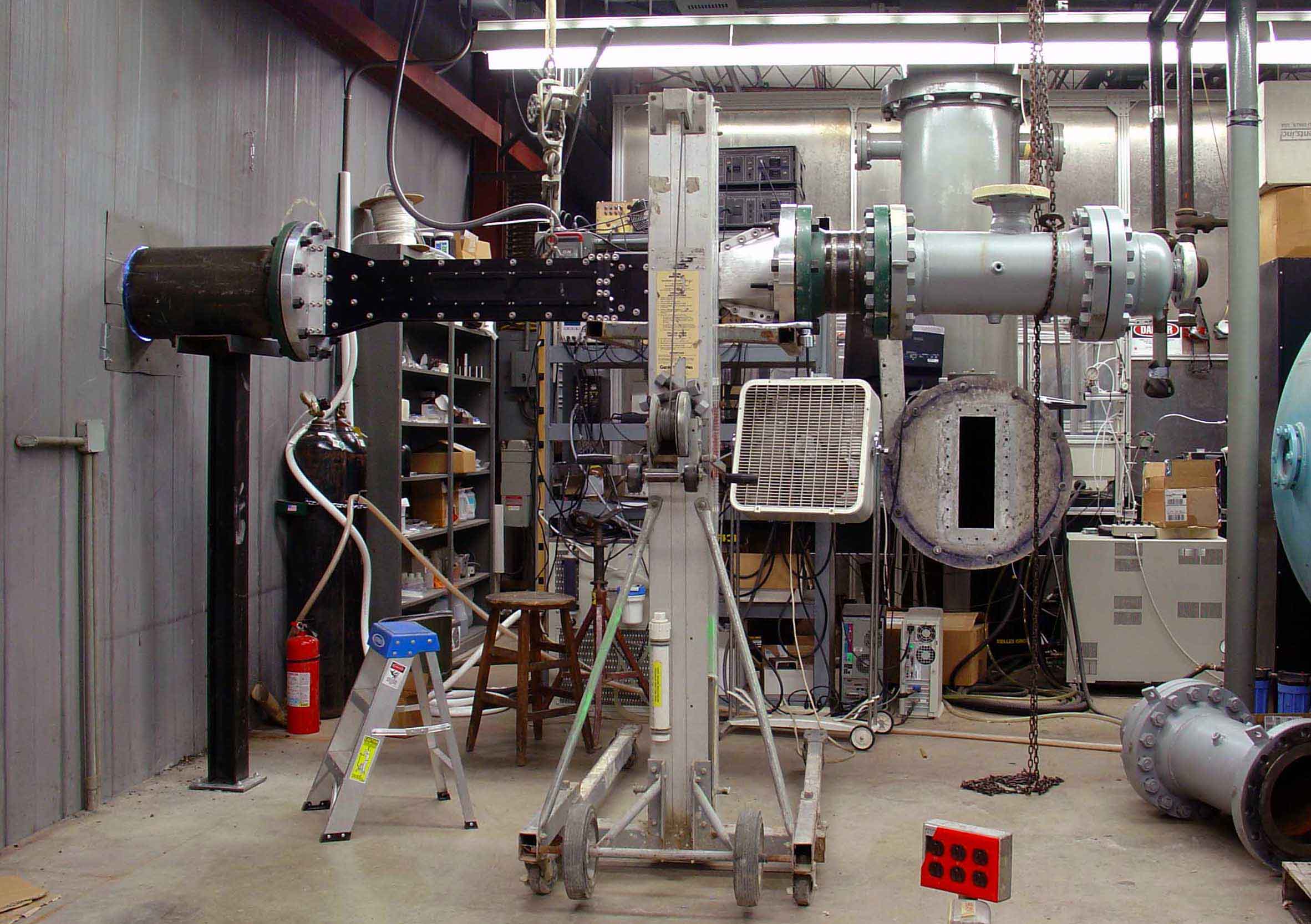
With the new air-supply system the cavity-flow facility C can operate in the full subsonic range. Finally a new, dual-stream shear layer facility S has been put on line, Figs. 2 and 4. This facility has a modular construction that allows it to be modified into a single stream, supersonic cavity-flow facility. |
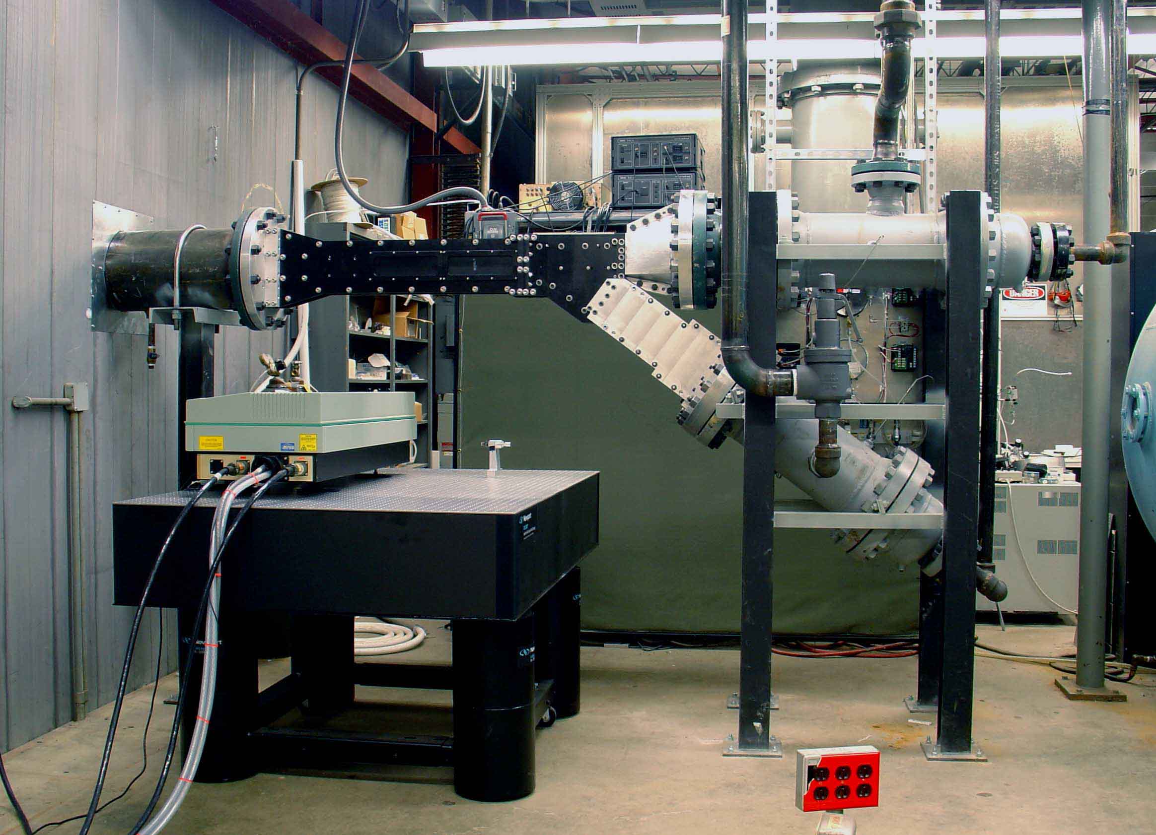 |
| Figure 4: Shear layer facility during construction (left), and completed (right). |
Besides granting a whole new series of experimental capabilities, the current air-supply system is very simple to use. In its design I included a safety logic scheme that does not allow operation if the system is improperly set and I put great emphasis in simple and effective ergonomics. After completing the acceptance and initial tests, this new system enabled the GDTL researchers to run a wider spectrum of experiments with an unprecedented level of convenience and comfort. |
| MD previous research | MD research | MD home |